Pin Descriptions
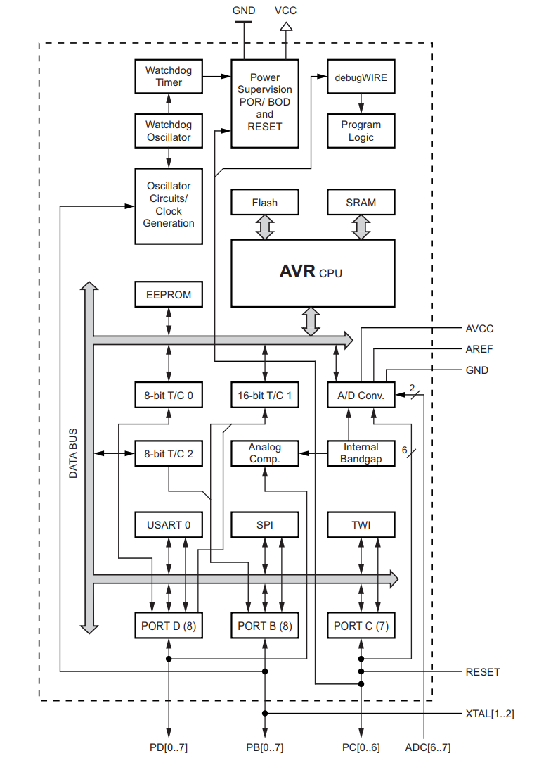
Block Diagrams from DataSheet ATMEL 7810: Page 6 Figure 2-1 & DataSheet ATMEL 42735: Page 14 Figure 5.1
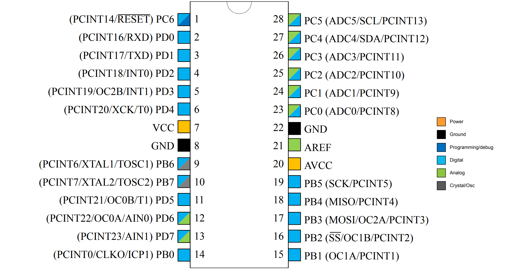
VCC
Power Supply:
- 2.7V to 5.5V for up to 8MHz
- 4.5V to 5.5V for up to 16MHz
GND
Ground.
AVCC
AVCC is the supply voltage pin for the A/D converter. It should be externally connected to VCC, even if the ADC is not used. If the ADC is used, it should be connected to VCC through a low-pass filter.
AREF
Analog reference pin for the A/D converter.
Port B (PB7:0)
Port B is an 8-bit bi-directional I/O port with internal pull-up resistors.
Port C (PC5:0)
Port C is a 7-bit bi-directional I/O port with internal pull-up resistors.
PC6/RESET
If the RSTDISBL Fuse is programmed, PC6 is used as an I/O pin. Note that the electrical characteristics of PC6 differ from those of the other pins of Port C.
If the RSTDISBL Fuse is unprogrammed, PC6 is used as a Reset input.
Port D (PD7:0)
Port D is an 8-bit bi-directional I/O port with internal pull-up resistors.
ADC7:6
In the TQFP and VFQFN package, ADC[7:6] serve as analog inputs to the A/D converter. These pins are powered from the analog supply and serve as 10-bit ADC channels.